“AI” PHYSICS – Energy Fields – Part 1.
Brian Strom. [1]
email: brianstrom999@aol.com
https://www.facebook.com/brian.strom.750
blog: https://edisconstant.wordpress.com/
Abstract:
In this paper on AI Physics, Artificial Intelligence is used to analyse simple experiments on energy fields (presently referred to as magnetic and electromagnetic fields). The AI searches for trends and patterns in the behavior of energy fields and the interactions between energy fields. The AI first observes the similarities between energy fields surrounding conductors, solenoids, permanent magnets and rotating bodies (such as the Earth). It examines the interactions between various energy fields, proposes new experiments, and predicts results. The AI concludes that energy fields will turn or move, if free to do so, to reduce the net field between them. From the behavior of permanent magnets, it is proposed that this movement will also reduce the total energy of the combined energy fields to a minimum.
.
1. Introduction:
Simple physics experiments have been conducted over the centuries and elaborate theories have been proposed to explain the observations (e.g. magnetic and electro-magnetic theories). These theories have become dominant and, in the modern era, they generally go unchallenged. This paper re-examines some fundamental aspects of physical behaviour and, with the help of Artificial Intelligence, proposes alternative explanations for the interactions in nature.
For this paper, AI is used to study old and new experiments on the nature of energy fields. The inputs to the AI are simple rules on observed energy fields, and the observed interactions between energy fields. To avoid controversy, the AI is not given any human theories on the unobservable detail at the atomic level. Instead, the AI develops in a step-by-step method, and reaches its own conclusions based upon its analysis of the perceived facts. The AI is given the following rules based on experimental observations:
1. A permanent magnet has an energy field around it. Opposite poles of permanent magnets attract each other, and same poles repel each other.
2. In a conductor, the flow of electrons from battery negative to battery positive, is a flow of energy which creates a circular energy field around the axis of the conductor.
3. The energy field around a current-carrying conductor can be observed by using a permanent magnet, in the form of a compass needle.
4. A compass needle (that points towards the Earth’s Arctic pole), will point anti-clockwise around the current-carrying conductor.
5. The strength of the energy field reduces as approximately the inverse square of the radial distance from the axis.
6. A rotating body can be treated as a toroidal flow of energy.
The AI uses these basic rules, with examples of observations, and gradually builds an understanding of the nature of energy fields, in a step-by-step manner.
It links together the observations and proposes new experiments, and predicts the results of these experiments.
.
2. Experiments with a current-carrying conductor:
For a conductor with an applied voltage (potential gradient), the accepted theory is that electrons move along the conductor from negative to positive. The electron flow is an energy flow and creates an energy field which can be observed – see Figure 2a.
The energy field is here shown to point anti-clockwise, and can be detected and examined with a compass needle. By observation, using a compass needle, the strength of the energy field can be shown to reduce approximately with the square of the distance from the centre of the conductor – see Figure 2b.
Note: In energy terms, the energy field is presumed to be caused by the traveling potential energy well of the electron. This cannot be proven by these experiments, and is not discussed further.

Figure 2a. Linear energy flow creates a circular energy field around axis of energy flow.
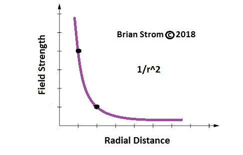
Figure 2b. Strength of energy field reduces inversely as square of distance from axis.
.
3. The energy field around a circular conductor – the solenoid:
By observation, the energy field around a circular current-carrying conductor is shown in Figure 3a:

Figure 3a. The energy field around a circular current-carrying conductor.
By observation, the energy field around multiple circular conductors – the solenoid – is shown in Figure 3b:

Figure 3b. The energy field around multiple circular conductors – the solenoid.
.
4. The energy field around a permanent magnet:
The energy field around a permanent magnet exhibits the same characteristics as that around a solenoid. The strength of the field can be shown to reduce approximately with the square of the distance from the centre of the magnet.
Because of the similarities in the characteristics of the energy fields of a solenoid and a permanent magnet, the AI proposes that the energy field around the permanent magnet is created, as in the solenoid, by some form of internal, circular or rotational energy flow – see Figure 4.
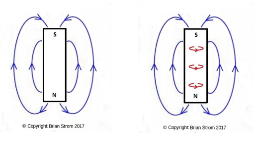 Figure 4: The energy field around a permanent magnet.
.
5. The energy field around a rotating body:
The AI is given the rule that the energy flow of a rotating body can be equated to a toroidal flow of energy – see Figure 5a. The rotating body may be of any shape: spherical, discoid or irregular.
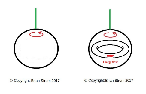
Figure 5a. A rotating body is equivalent to a toroidal flow of energy.
The AI proposes that the toroidal energy flow in a rotating body creates an energy field in the same way as the energy flow in a conductor, solenoid or magnet – see Figure 5b:

Figure 5b. The energy field around a rotating body.
.
6. Similarities and interchangeability between energy fields:
The AI notes the similarities and proposes full interchangeability between the energy fields of the solenoid, permanent magnet and rotating body. For diagrammatic representation – see Figure 6a. For visual representation – see Figure 6b.
Note: From experimentation with irregular-shaped energy fields, the strength of the field can be shown to reduce somewhere between the square and cube of the distance from the centre of the object. In mathematical terms, the strength of the energy field reduces inversely with r^x where r is the distance from the effective centre of the object, and x is a power usually between 2 and 3.
 Figure 6a: The similarities of observed energy fields – diagrammatic.
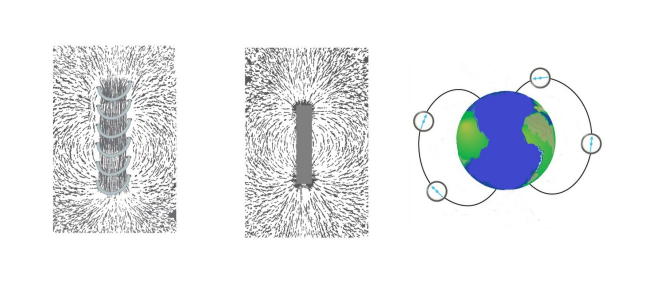
Figure 6b: The similarities of observed energy fields – visual.
.
7. Interaction between energy fields around linear conductors:
The AI is given information on the observed behavior of a compass needle in the vicinity of two parallel current-carrying conductors.
When the currents are in opposite directions, the energy fields between the conductors are in the same direction such that they reinforce each other. With a stronger net field between the two conductors than on the outside of the conductors, the conductors are seen to move apart, along the energy field gradient.
When the currents are in the same direction, the energy fields between the conductors are in opposite directions such that they tend to cancel each other. With a stronger net field remaining on the outer sides of the conductors, the conductors will move together, along the energy field gradient. See Figure 7:

Figure 7: Interaction between energy fields around conductors.
.
8. Interaction between a compass needle and other energy fields:
From observation, if free to turn, a permanent magnet (in the form of a compass needle) and its energy field will turn to oppose an adjacent energy field. This will reduce and minimize the combined field strength of the two energy fields. For instance, a compass needle will turn to minimize the net field between it and the Earth’s energy (magnetic) field – see Figure 8a:
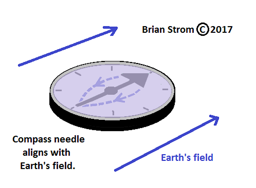
Figure 8a: Interaction between energy field of compass needle and Earth’s energy field.
As another example, a compass needle will turn to minimize the net field between it and a current-carrying conductor – see Figure 8b. The movement of the compass needle near a current-carrying conductor was studied in experiments by Ørsted. [2]
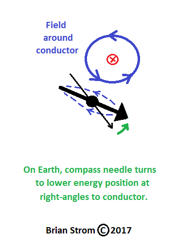
Figure 8b: Interaction between compass needle and current-carrying conductor.
The AI proposes that, if free to move, a permanent magnet (in the form of a compass needle) and its energy field will turn and also move toward a position of lower net field strength. For instance, a compass needle, floating in a dish of water, will turn to oppose the field around the conductor and also move toward a central, symmetric position beneath the conductor. The AI proposes that the net energy field between the compass and conductor will be a minimum in this configuration – see Figure 8c:
Note: This result has been confirmed by experiment.
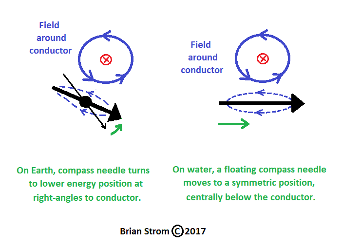
Figure 8c: Interaction between floating compass needle and the energy field around a current-carrying conductor.
The AI proposes that, if free to move in three dimensions, a permanent magnet (in the form of a compass needle) and its energy field will move toward a position of minimum net field strength. For instance, a compass needle, in zero gravity, will turn to oppose the field around the conductor. The compass needle will also move toward a central, symmetric position near the conductor. The AI proposes the compass needle will also move toward the conductor – and its minimum net energy field position will be when adjacent and in contact with the conductor – see Figure 8d:
Note: This result has yet to be confirmed by an experiment in zero gravity.
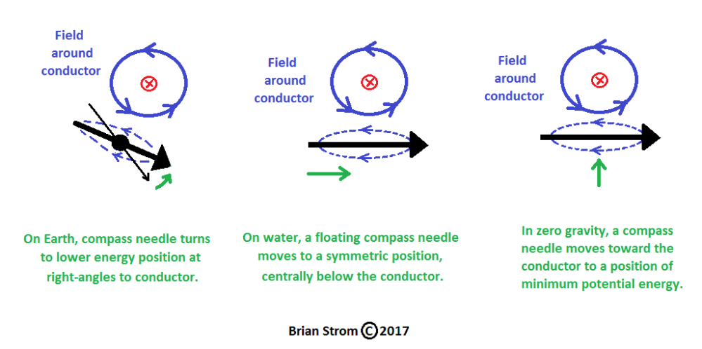
Figure 8d: Interaction in zero gravity between compass and energy field around conductor.
.
9. Interaction between energy fields of permanent magnets:
For two permanent magnets, side-by-side, with same rotation/spin (poles pointing in the same direction), the energy field between the magnets will tend to reinforce and strengthen. With a stronger net field between the two magnets and a weaker field outside the magnets, the two magnets will tend to move apart – see Figure 9a:

Figure 9a: Permanent magnets: side-by-side: same rotation/spin: move apart.
For two permanent magnets side-by-side, with opposite rotation/spin (poles pointing in opposite directions), the energy field between the magnets will tend to cancel and weaken. With a weaker net field between the two magnets and a stronger field outside the magnets, the two magnets will tend to move together – see Figure 9b:

Figure 9b: Permanent magnets: side-by-side: opposite rotation/spin: move together.
For two permanent magnets, end-to-end, with same rotation/spin (poles also pointing in the same directions), the energy field between the magnets will tend to cancel and weaken. With a weaker net field between the two magnets and a stronger field outside the magnets, the two magnets will tend to move together – see Figure 9c:

Figure 9c: Permanent magnets: end-to-end: same rotation/spin: move together.
For two permanent magnets, end-to-end, with opposite rotation/spin (poles also pointing in the opposite directions), the energy field between the magnets will tend to reinforce and strengthen. With a stronger net field between the two magnets and a weaker field outside the magnets, the two magnets will tend to move apart – see Figure 9d:

Figure 9d: Permanent magnets: end-to-end: opposite rotation/spin (same poles): move apart.

Figure 9e: Summary of interactions between energy fields of permanent magnets.
.
10. Interaction between energy fields of rotating bodies:
The AI proposes that for two non-magnetic spheres, side-by-side, rotating in the same direction, the energy field between the spheres will tend to reinforce and strengthen. With a stronger net field between the two spheres than outside the spheres, the spheres will tend to move apart, along the energy field gradient, to a position of lower net field strength – see Figure 10a.

Figure 10a: Interaction between energy fields around rotating bodies.
The AI proposes that for two non-magnetic spheres, side-by-side, rotating in opposite directions, the energy field between the spheres will tend to cancel and weaken. With stronger fields remaining on the outer sides, and a weaker net field between the two spheres, the spheres will tend to move together, along the energy field gradient, to a position of lower net field strength – see Figure 10b:

Figure 10b: Interaction between energy fields around counter-rotating bodies.
The AI proposes that for two non-magnetic spheres, end-to-end, rotating in the same direction, the energy field between the spheres will tend to cancel and weaken. With stronger fields remaining on the outer sides, and a weaker net field between the two spheres, the spheres will tend to move together, along the energy field gradient, to a position of lower net field strength – see Figure 10c:

Figure 10c: Rotating bodies end-to-end: same rotation/spin: move together.
The AI proposes that for two non-magnetic spheres, end-to-end, rotating in opposite directions, the energy field between the spheres will tend to reinforce and strengthen. With a stronger net field between the two spheres than outside the spheres, the spheres will tend to move apart, along the energy field gradient, to a position of lower net field strength – see Figure 10d.

Figure 10d: Rotating bodies end-to-end: opposite rotation/spin: move apart.

Figure 10e: Summary of interactions between energy fields of rotating bodies.
.
11. Interaction between energy fields of solenoids:
The AI proposes the same results for the energy fields around solenoids, and this has been confirmed by experiment. See Figure 11.

Figure 11: Summary of interactions between energy fields of solenoids.
.
12. Substitution of energy fields:
The AI proposes that the same results will occur if one type of energy field (permanent magnet, rotating body or solenoid) is replaced with any other type (permanent magnet, rotating body or solenoid). The AI proposes that one energy field can be substituted for any other type of energy field – see Figure 12:

Figure 12: Interactions between different energy fields.
The results will depend on the comparative strengths of the energy fields. On Earth, we observe strong energy fields around conductors and solenoids. The energy fields around permanent magnets are less strong.
The energy fields around visible rotating bodies are weaker still, including the Earth’s energy field (presently called the Earth’s magnetic field).
.
13. Interchangeability of energy fields:
The interchangeability of energy fields can be shown as a composite diagram – see Figure 13a – and a summary of the full interchangeability of energy fields, and their interactions, is shown in Figure 13b:

Figure 13a: Composite diagram showing interchangeability of energy fields.

Figure 13b: Summary of interactions between energy fields (composite).
.
14. Addition and subtraction of mixed energy fields:
The AI proposes an experiment to combine the energy field of a rotating object with the energy field of a permanent magnet. By rotating a permanent magnet, its total energy field can be increased or decreased, depending on the direction of rotation.
The increase/decrease in the energy field can be demonstrated with a “floating” magnet above the rotating magnet. The “floating” magnet will rise or fall with the increase/decrease in the energy field of the rotating magnet – see Figure 14:
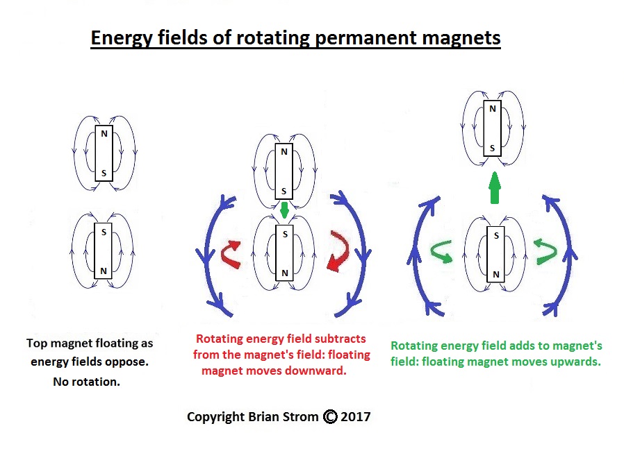
Figure 14: Interaction of energy fields of rotating magnets.
.
15. Movement to minimum total energy position:
From observation, two permanent magnets, if free to do so, will move towards each other until opposite “poles” are in contact. It is assumed that the magnets are moving to a position of lower field strength. It is also assumed that this will be the position of lower total energy.
If the magnets come to rest in an end-to-end position, this will be an unstable equilibrium configuration. The magnets will easily flip to a side-by-side configuration which will be a stable equilibrium. It is assumed that this side-by-side configuration is the position for minimum net field strength. It is also assumed that this will be the position of minimum total energy.
Note: In an externally applied energy field (e.g. magnetic field for Nuclear Magnetic Resonance) – the individual energy fields can be imagined as all aligning with the applied field. Upon removal of the applied field, some individual energy fields will flip back to their lower energy positions.
Note: Whilst a permanent magnet or solenoid can easily “flip” to a position of lower energy, a rotating body cannot normally flip and change its spin vector without an energy input.

Figure 15: Minimum energy configurations for energy fields.
.
16. Summary and conclusions:
The AI notes the similarities between energy fields and proposes full interchangeability between the energy fields of the solenoid, permanent magnet and rotating body.
From the observations on the behavior of conductors, compass needles and permanent magnets, the AI concludes that energy fields will interact with each other, and will turn or move, if free to do so. The movement will be to positions of lower net field strength, which will also be positions of lower total energy.
This set of experiments attempts to demonstrate the interaction between energy fields at the laboratory scale, and within the Earth’s energy (magnetic) field. Various experiments have been proposed, and some results published, where different types of energy-field probes have been placed near rotating flywheels. Other experiments have attempted to monitor changes in the decay rate of radio-isotopes in the presence of other energy-fields, including that of the Sun. Changes from standard within the range 1 in 10^-4 and 1 in 10^-10 have been reported. This paper may provide a theoretical basis for further experimental studies.
Note: Experiments are underway in London (UK), Cambridge (Ma) and Birmingham (UK) to quantify the effects of energy field interactions.
Further information is on this Blog: https://edisconstant.wordpress.com/
.
17. References:
[1] Brian STROM. “AI” Physics – Atomic Structure: Part 1. viXra:1811.0162 November 2018.
[2] John Christian ØRSTED. “Experiments on the Effect of a Current of Electricity on the Magnetic Needle (1820).”
.
Copyright © 2018 Brian Strom. All rights reserved.
========================================================
